MIL-DTL-27599D
Series I
Series II
Contact
A
C
D
E
F
G
H
J max
J max
size
min
+.005
-.000
22D
.0305
.036
.037
.114
.049
.080
.058
.379
.038
.0295
.034
.094
.047
.050
22M
.0305
.036
.033
.114
.046
.080
.058
.379
.038
.0295
.028
.094
.043
.050
22
.0305
.036
.040
.114
.054
.080
.058
.379
.038
.0295
.035
.094
.051
.050
20
.041
.045
.048
.145
.066
.100
.085
.379
.038
.039
.042
.125
.060
.068
16
.0635
.067
.082
.161
.103
.100
.107
.379
.038
.0615
.069
.141
.097
.068
Inches
mm
Inches
mm
Inches
mm
Inches
mm
Inches
mm
.028
0.71
.038
0.97
.048
1.22
.066
1.68
.100
2.54
.0295
0.749
.039
0.99
.049
1.24
.067
1.70
.103
2.62
.0305
0.774
.040
1.02
.050
1.27
.068
1.73
.107
2.72
.033
0.84
.041
1.04
.051
1.30
.069
1.75
.114
2.90
.034
0.86
.042
1.07
.054
1.37
.080
2.03
.125
3.18
.035
0.89
.043
1.09
.058
1.47
.082
2.08
.141
3.58
.036
0.91
.045
1.14
.060
1.52
.085
2.16
.145
3.68
.037
0.94
.046
1.17
.0615
1.562
.094
2.39
.161
4.09
.047
1.19
.0635
1.613
.097
2.46
.379
9.63
NOTES:
1. Dimensions are in inches. Metric equivalents are given for information only.
2. Size 16 contacts shall refuse entry to A .071 (1.80 mm) maximum diameter pin; size 20 contacts
shall refuse entry to A .048 (1.22 mm) maximum diameter pin; size 22D contacts shall refuse
entry to A .038 (0.97 mm) maximum diameter pin; size 22M contacts shall refuse entry to A .038
(0.97 mm) maximum diameter pin; size 22 contacts shall refuse entry to A .038 (0.97 mm)
maximum diameter pin.
3. Dimensions shown affect interchangeability, function, and fit; unless specified, other design
features are optional.
4. An .040 ± .001 (1.02 ± .03 mm) diameter pin for size 20 contacts; an .0625 ± .0010 (1.588 ±0.025
mm) diameter pin for size 16 contacts; an .0300 ± .0005 (0.762 ± .013 mm) diameter pin for 22D
contacts; an .0300 ± .0005 (0.762 ± .013 mm) diameter pin for 22M contacts; an .0300 ± .0005
(0.762 ± .013 mm) diameter pin for size 22 contacts; must enter socket to the depth indicated; the
pin shall be radiused in accordance with the dimensions indicated herein.
5. Dimension "H" is ID of insert entry hole.
6. Sharp edges are not permissible.
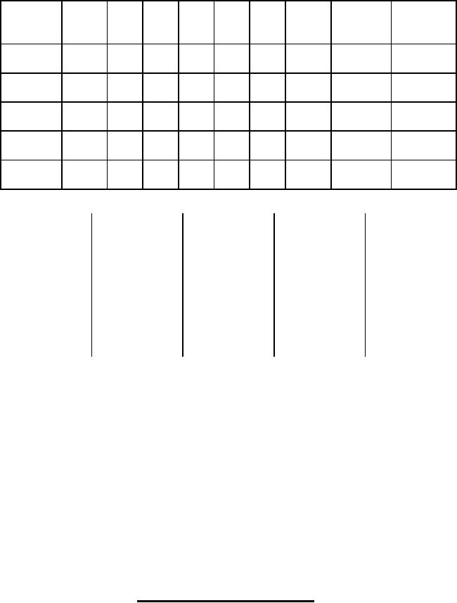
FIGURE 6. Contact configuration and dimensions Continued.
43
For Parts Inquires submit RFQ to Parts Hangar, Inc.
© Copyright 2015 Integrated Publishing, Inc.
A Service Disabled Veteran Owned Small Business