MIL-DTL-28748D
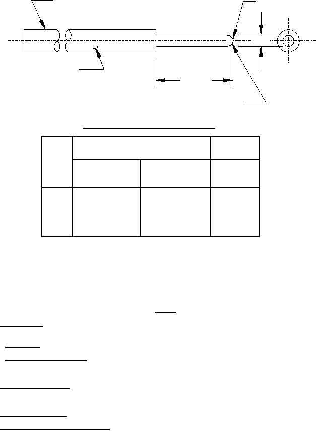
HANDLE SHOWN TYPICAL
B
RECOMMENDED LENGTH 1.0000
MINIMUM DIAMETER TWICE "A" MAX
A
STAMP GAUGE WITH
M28748-# OR MS 3197-#
.500 MIN
RADII SHALL BE SMOOTHLY
BLENDED INTO PIN DIAMETER
Test pins for measuring contact separating forces.
Contact
A
B
size
(mm)
and
dash
Minimum diameter
Maximum diameter
Max
number
+.0001 (0.003)
+.0000
flat
-.0000
-.0001 (0.003)
(mm)
16X1
0.0615 (1.56)
.015 (0.38)
16Y1
---
.015 (0.38)
0.0635 (1.61)
20X1
0.0390 (0.99)
.007 (0.18)
20Y1
---
0.0410 (1.04)
.007 (0.18)
22X1
0.0295 (0.75)
.007 (0.18)
22Y1
0.0305 (0.77)
---
.007 (0.18)
NOTES:
1. Dimensions are in inches.
2. Metric equivalents are given for general information only.
3. Material: Gauge pin for contact sizes 22 and 20, tool steel or tungsten carbide, and for contact size 16, tungsten carbide.
4. Finish: 6 to 10 microinches root mean square determined in accordance with ASME B46.1.
5. No plating.
6. These gauges are intended for use with electric connector socket contacts referenced in this document and in MIL-C-39029.
FIGURE 7. Test pin.
4.7.19 Finish thickness. Finish thickness of the plating and strikes shall be determined by any method which will give results
within ±.010 percent of the true thickness.
4.7.19.1 Overall finish. Plating thickness shall be measured on the external surfaces of the contact body.
4.7.19.2 Localized finish (see 3.3.5.2.2). Finished thickness shall be .00005 inch (0.00127 mm) minimum thickness of deposited
gold. Measurements shall be made at point B or C (see figure 1) as applicable. However, the plating on non-significant surfaces,
nonfunctional surfaces shall be sufficient thickness to ensure plating continuity and uniform appearance.
4.7.20 Industrial gas (see 3.5.17). Unmated contacts shall be placed on a noncorrosive rack in a closed plastic or glass chamber
(volume 2 cubic feet maximum) which contains a 10 percent solution of sulphurated potash NF in distilled water. Contacts shall not
be immersed in the solution but shall be exposed to the sulfide vapor for 100 hours.
4.7.21 Solderability (see 3.5.18). Solder type contacts shall be tested in accordance with method 208 of MIL-STD-202.
4.7.22 Resistance to soldering heat (see 3.5.19). All connectors with solder terminations shall be tested in accordance with EIA-
364-56. The connectors shall be tested in accordance with procedure 1, unless otherwise specified (see 3.1).
25
For Parts Inquires submit RFQ to Parts Hangar, Inc.
© Copyright 2015 Integrated Publishing, Inc.
A Service Disabled Veteran Owned Small Business