MIL-DTL-28748D
4.7.9 Humidity (see 3.5.7 and figure 4). Unmated plugs and receptacles shall be tested in accordance with method 1002, type II,
of MIL-STD-1344, except steps 7A and 7B are not required. The following details shall apply:
a. Initial measurements: No measurements are required after initial conditioning, nor voltage applied to
connectors during exposure.
b. Final measurement: After completion of step 6 of the final cycle, but no sooner than 1-1/2 hours and not later than 3
hours while the sample is still in the chamber, insulation resistance shall be measured as specified in 4.7.4 Following the
insulation resistance test, dielectric withstanding voltage shall be tested as specified in 4.7.5, except the magnitude of test
voltage shall be in accordance with table III for a period of 5 minutes, applied between all contacts and the shell.
4.7.10 Vibration (see 3.5.8). Complete mated connectors shall be tested in accordance with method 2005, test condition II of MIL-
STD-1344.
a.
At the conclusion of this test, the connector assembly shall be visually examined for loosening, fracture,
or other deterioration (see 3.3.7).
4.7.11 Shock (specified pulse) (see 3.5.9). Complete mated connectors shall be tested in accordance with method 2004 of MIL-
STD-1344. The following details shall apply:
a.
Mounting method: In accordance with the mounting fixture in method 2005 of MIL-STD-1344.
b.
Test condition I.
c.
Measurements: Contacts shall be monitored for electrical continuity during test and connectors shall be
examined for evidence of failure of metallic or dielectric materials and engagement of the mated portions
after test.
4.7.12 Insertion and withdrawal force (connector assembly) (see 3.5.10). Each connector, with full complement of contacts, shall
be mated and unmated. The insertion and withdrawal forces, applied gradually, shall be measured after three cycles.
4.7.13 Durability (see 3.5.11). The complete connector assemblies shall be subjected to 500 cycles of insertion and withdrawal at
a rate not to exceed 500 cycles per hour. Tests shall be conducted using normal engaging hardware. The insertions and
withdrawals shall be accomplished in a manner similar to that which the connectors shall be subjected in service.
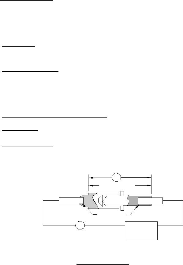
4.7.14 Contact resistance (see 3.5.12). The potential drop across each mated pair of pin and socket contacts shall be measured
at rated current as shown in table V. Potential drop readings shall be taken across the two points as shown on figure 6 (A-A).
Measurements shall be taken after the temperature of the wire has stabilized and readings shall comply with the initial test values
shown in table V.
V
MILLIVOLT A-A
CABLE
CABLE
SOLDERED
A
POWER
SUPPLY
FIGURE 6. Voltage drop test wiring diagram.
23
For Parts Inquires submit RFQ to Parts Hangar, Inc.
© Copyright 2015 Integrated Publishing, Inc.
A Service Disabled Veteran Owned Small Business