MIL-DTL-25955A
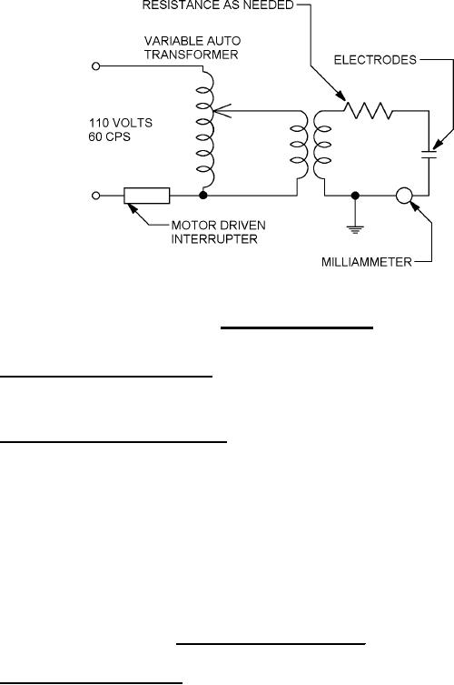
FIGURE 5. Arc resistance test circuit.
4.6.17 Dielectric strength test (see 3.6.17). Disc specimens of insert in accordance with ASTM-D5948
shall be conditioned in accordance with ASTM-D5948. The specimens shall be then be subjected to the
step-by-step test of ASTM-D5948.
4.6.18 Dimensional stability test (see 3.6.18). Insert material bar specimens 5 x ½ x ½ inches shall be
molded by the manufacturer. The ½ x ½ inch ends shall be machined smooth and parallel as necessary
for this test. There shall be no post mold treatment. Within 10 days after removal from the mold, test of
the specimens shall be initiated as specified below.
a. Preconditioning shall consist of 96 hours at 25°C (77°F) and 50 percent relative humidity.
b. The initial length shall then be measured to the nearest .001 inch.
c. The specimens shall then be cycled in a circulating oven at 125° ± 5°C (257° ± 9°F) for a period
of 48 hours followed by 25° ± 5°C (77° ± 9°C) and 50 percent relative humidity for 24 hours.
d. After 10 cycles as specified in 4.6.17c above, the final length of the specimen shall be measured.
e. The following relationship shall be employed to calculate the percentage change in the length.
I (initial length) F (final length)
D (percent change) =
X 100
I
4.17.9 Air leakage test (see 3.6.19.6). Class H receptacles shall be mounted in a suitable test
apparatus for the application of the specified test pressure across the connectors. Prior to test, at least
10 percent with a minimum of three of the contacts shall have suitable wires soldered into normal service
positions. Conventional solder and techniques shall be employed satisfactory for military application. A
suitable means to determine the leakage of air or of pressurized gas, containing not less than 10 percent
helium by volume, through the connector shall be employed while the specified pressure is applied.
26
For Parts Inquires submit RFQ to Parts Hangar, Inc.
© Copyright 2015 Integrated Publishing, Inc.
A Service Disabled Veteran Owned Small Business