MIL-DTL-26500G
NOTES:
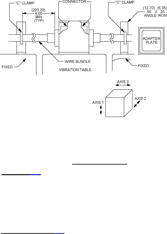
1. Dimensions are in inches.
2. Metric equivalents are in parentheses.
3. Unless otherwise specified, tolerance is ± .02 inch (0.51 mm).
4. Mounting bracket .25 inch (6.35 mm) steel construction.
FIGURE 2. Vibration testing equipment.
4.6.12 Humidity (see 3.16). The mated and wired connectors shall be tested in accordance with test
procedure EIA-364-31, with the following exceptions and details:
a. Test condition - Method III, omitting subcycle step 7b.
b. There shall be no drip loops in the wires.
c. Wires shall be brought out of the chamber through vapor-tight seals.
d. There shall be no wire splices in the chamber.
e. Upon completion of step 6 of the final cycle, while the connectors are still subjected to high
humidity, the insulation resistance shall be measured.
f. The class H receptacles shall not be enclosed for this test, but shall be blown dry before the
insulation resistance measurements.
4.6.13 Insulation resistance (see 3.17). The connectors shall be tested on accordance with test
procedure EIA-364-21. For test purposes, the resistance shall be measured separately between the
closest three pairs of adjacent contacts, which were inserted and removed 10 times in maintenance aging
and between the contact closest to the shell and the shell.
23
For Parts Inquires submit RFQ to Parts Hangar, Inc.
© Copyright 2015 Integrated Publishing, Inc.
A Service Disabled Veteran Owned Small Business