MIL-DTL-26518C
3.5.2.3 Contact alignment.- Inserts for socket contacts shall be so designed that individual contacts will have an overall side play
of 0.005 inch (0.13 mm) minimum and 0.015 inch (0.38 mm) maximum at a bending moment of 0.25 inch-pound force (1.11 N) for
size 20 and 1 inch-pound force (0.44 N) for sizes 16, 12, and shielded contacts. This requirement applies to unwired contacts.
3.5.2.4 Contact arrangement.- The contact arrangement in inserts shall be as specified by the connector part number and in
accordance with the applicable military standards.
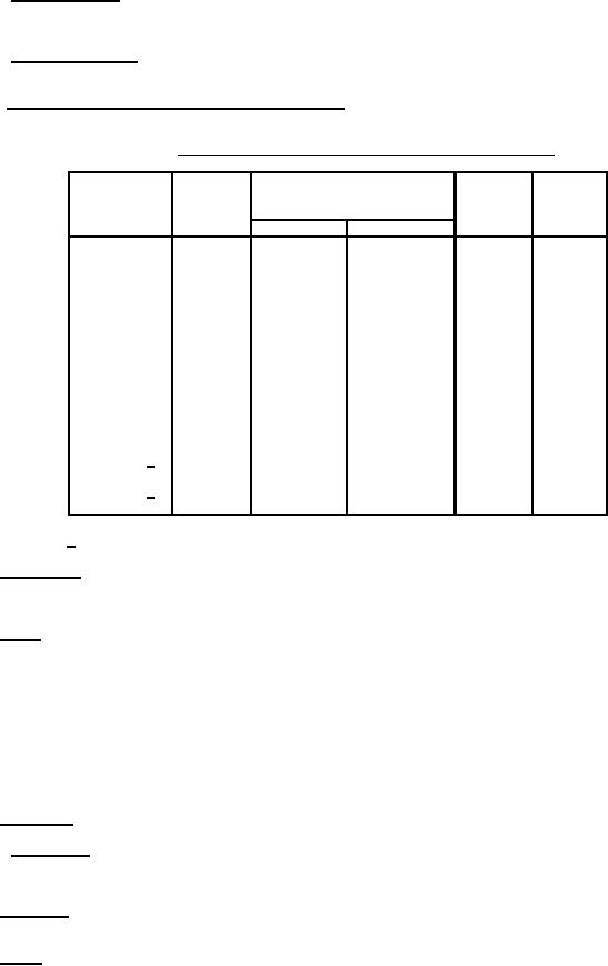
3.5.2.5 Contact sizes, wire accommodations, and current ratings. Contact sizes, wire accommodations, and current ratings shall
be in accordance with table I.
TABLE I. Contact sizes, wire range accommodations, and current ratings.
Test
Wire range accommodations
Current
current
Contact
Wire size
OD
ratings
amperes
size
amperes
Min (mm)
Max (mm)
20
24
0.040 (1.01)
0.090 (2.28)
3.0
3.0
20
22
0.040 (1.01)
0.090 (2.28)
5.0
5.0
20
20
0.040 (1.01)
0.090 (2.28)
7.5
7.5
16
18
0.068 (1.73)
0.130 (3.30)
16.0
10.0
16
16
0.068 (1.73)
0.130 (3.30)
22.0
13.0
12
14
0.106 (2.69)
0.170 (4.32)
32.0
17.0
12
12
0.106 (2.69)
0.170 (4.32)
41.0
23.0
1 shielded 1/
22
0.096 (2.44)
0.120 (3.05)
3.0
3.0
2 shielded 2/
20
0.095 (2.41)
0.145 (3.68)
7.5
7.5
1/ Size 1 shielded contacts conform to M39029/54.
2/ Size 2 shielded contacts conform to M39029/55.
3.5.3 Sealing plugs. Insulated plugs shall be inserted following unwired contacts, except in the case of shielded contacts the
unwired contacts shall not be inserted. The plugs shall be in accordance with MS27488. The same sealing plug shall be used in both
the connector plug and receptacle.
3.5.4 Inserts. The inserts shall be designed and constructed with proper sections and radii so that they will not readily chip,
crack, or break in assembly or normal service. Hollow-type inserts shall not be used. The insert shall be so designed and constructed
as to eliminate all air paths between contacts. The pin insert shall have a dynamic peripheral seal, which will contact the mating
connector shell before mating is completed. The socket insert shall be resilient and designed with an integral-molded static peripheral
seal that will contact the mating connector insert before insert faces contact each other. A peripheral recess shall be provided in the
class R pin insert to accept the socket insert seal, as shown on the applicable detail document. Inserts and shells shall be so
designed and constructed that the inserts cannot be removed from the shell. The entire insert and wire-sealing member shall either
be one integral part or be bonded and shall provide suitable sealing around the wire having overall diameters of the range shown in
table I. The inserts shall be so designed that positive locking of the contacts in the inserts is provided. The wire-sealing member shall
not be removable from the shell. Contacts for class H connectors shall be fused into a single insert of vitreous material. No metal
lattice material shall be used between contacts. A resilient face gasket shall be cemented to the vitreous face.
3.5.5 Shell design. The connectors shall be of the solid shell design and shall be constructed to positively retain inserts.
3.5.5.1 Mating shells. The shells and their mating inserts shall be designed to achieve a face-to-face resilient seal. This seal,
together with the integral peripheral seal, is intended to insure that mated connectors will comply with the performance requirements
specified herein.
3.5.6 Back shells. When compressed about the wires and contacts by the back shell, the sealing member shall not distort or bind
any of the contacts to cause improper operation of the connector.
3.5.7 Weight. The weight of plug and receptacle assemblies shall not exceed the values specified in the applicable military
standards.
4
For Parts Inquires submit RFQ to Parts Hangar, Inc.
© Copyright 2015 Integrated Publishing, Inc.
A Service Disabled Veteran Owned Small Business