MIL-DTL-21097G
NOTES:
1. Dimensions are in inches
2. Metric equivalents are given for general information only.
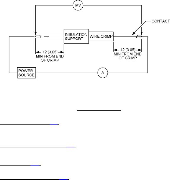
FIGURE 7. Crimp contact resistance.
4.6.18 Current cycling (crimp) (see 3.22). Test samples attached to 3-foot lengths of appropriate wire shall be
subjected to 50 current cycles. Each cycle shall consist of 30 minutes at 125 percent of the test current specified in
table VI, followed by 15 minutes at no load. Voltage drops shall be measured at test current specified in table VI after
the test assembly has returned to room temperature.
4.6.19 Crimp tensile strength (type CR) (see 3.23). Samples for test shall be placed in a standard tensile testing
machine and sufficient force applied at an approximate rate of 1 inch per minute to pull the wire out of the sample or
break the wire or sample.
4.6.20 Solderability (see 3.25). Contact terminals, except wrappost and crimp shall be subjected to method 208 of
MIL-STD-202.
4.6.21 Resistance to soldering heat (see 3.26). All connectors with solder terminations shall be tested as specified in
method 210 of MIL-STD-202, condition C, except connectors with solder cup terminations shall be tested in accordance
with the following details:
a. The applicable wire size properly prepared for the solder cup size shall be inserted into the contact
termination. A minimum of seven contacts shall be tested.
b. An appropriately prepared resistance soldering iron with an appropriate tip shall be applied to the lower
portion of the solder cup configuration where the wire enters the termination.
c. The solder shall be applied in the normal manner.
d. The resistance soldering iron shall be applied to the system. The wattage shall be adjusted as to obtain a
proper solder fillet in a minimum of 4 seconds.
e. After application, the soldering iron shall be removed and a visual and mechanical inspection performed.
f. Visual inspection shall be at 1X. The connector shall show no evidence of distortion or damage to any area
of the connector housing. The contact shall meet the contact retention requirement (4.6.6).The contact shall
not interfere with normal floating conditions as applicable and shall meet applicable location dimensions.
26
For Parts Inquires submit RFQ to Parts Hangar, Inc.
© Copyright 2015 Integrated Publishing, Inc.
A Service Disabled Veteran Owned Small Business