MIL-DTL-21097G
4.6.13 Humidity (see 3.17). The unmated connector, receptacle and mating half shall be tested in accordance with
test procedure EIA-364-31. The following details shall apply:
a. Test condition A, method II.
b. Final measurement Following this test, the connectors shall be subjected to the insulation resistance test
specified in 4.6.3.
4.6.14 Durability (board side) (see 3.18).
4.6.14.1 Types A and AD. The connectors shall be subjected to 500 insertions of a maximum thickness flat steel
gage at a rate of 400 to 600 cycles per hour. The dimensions of the gages shall be as specified on figure 3. Upon
completion of the conditioning, the resistance of contacts shall be measured as specified in 4.6.5 and the individual
contact separation force shall be measure as specified in 4.7.6.1.1.
4.6.14.2 Type CR. Composite connector receptacles and mating contacts assembled on the nominal thickness
printed wiring test board as specified (see 3.1) shall be subjected to 500 cycles of insertion and withdrawal at a rate of
400 to 600 cycles per hour. Upon completion of the conditioning, the resistance of contacts shall be measured as
specified in 4.6.5 and the individual contact separation force shall be measured as specified in 4.6.6.1.2.
4.6.15 Salt spray (corrosion) (see 3.19). The mated connector receptacle and printed wiring board or receptacle and
the nominal thickness standard printed wiring test board shown on figure 2 shall be tested in accordance with test test
procedure EIA-364-26, condition B.
4.6.16 Low-signal level contact resistance (see 3.20). Connectors shall be tested in accordance with test procedure
EIA-364-23 with the following exception. In lieu of requirement 3 (b), the test samples shall be terminated by two wires
on each contact. The connectors shall be mated with the printed wiring board. One of the wires shall provide a (series)
current lead circuit between contacts and the second wire shall provide a (parallel) contact resistance (voltage drop)
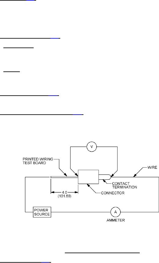
measuring point lead. For test points, see figure 6.
NOTES:
1. Dimensions are in inches
2. Metric equivalents are given for information only.
FIGURE 6. Resistance of contacts types A and AD.
4.6.17 Crimp resistance (see 3.21). The potential drop across each contact crimp shall be measured at rated current
as specified in table VI. Potential drop readings shall be taken across the two points as specified on figure 7.
Measurements shall be taken after the temperature of the wire has stabilized and readings shall comply with the initial
test values specified in table VI.
25
For Parts Inquires submit RFQ to Parts Hangar, Inc.
© Copyright 2015 Integrated Publishing, Inc.
A Service Disabled Veteran Owned Small Business